Use this useful chart to estimate the required length of your auger when trying to achieve a specific discharge height and angle of auger incline.
The site for hard to find mathematical formulas pertaining to grain handling and storage. Get grain handling and storage ideas here! Figure auger capacity, conveyor capacity and bucket elevator capacity.
Thursday, April 21, 2022
Friday, July 21, 2017
A good source for online grain (& feed) handling calculators
Here is a list of their current offering of calculators as of July 2017. I happen to know that they are always adding more though so bookmarking their page might be a good thing.
ONLINE CALCULATORS
- Calculate electric motor horsepower required to drive a hydraulic pump
- Calculate belt length and distance between pulleys
- Calculate Auger RPM
- Convert BPH to TPH (U.S. or Metric)
- Calculate feed density
- Convert cubic feet to tons
- Calculate feed truck capacity needed to obtain given tonnage
Friday, May 13, 2016
How Tall Should Your Bucket Elevator Be?
Maybe you are thinking about putting up a bucket elevator and want to get some rough estimates on costs? Maybe you've gotten bids from several contractors to put up a bucket elevator, but the bids came back with different elevator heights? What should it cost to put up a bucket elevator? To answer these questions, first you need to know the answer to the question, "how tall should my bucket elevator be?"
The height of your bucket elevator is determined by three factors: Required spout angle. How far away do you need to spout? How tall is your highest discharge point?
You'll find that there are a lot of opinions about what is correct, and what you might "get away with" when it comes to spout angle. The safe rule of thumb is, dry grain typically flows reliably in a spout at an angle of 45° or more. High moisture grain, sunflowers and ground feed generally require spouts at a minimum angle of 60°.
You might hear some say, "you don't need to be at 45° with your leg spouts. You can get by with 43° or even 40°. Working within these shallower spout angles is a way for some to shorten the height of the leg they are bidding. Buyer beware! While you might save a couple bucks putting up the elevator leg that is the shortest, it is generally not the place to try and save money. Remember, if the bucket elevator you install is too short, it is very difficult (read:expensive) to fix later. If your material can't efficiently flow down your spouts at the rated capacity of the rest of the upstream system, you'll have to slow all the equipment down upstream. This obviously reduces your throughput and increases your unload time. In a particularly bad scenario, overfeeding a spout at too shallow of an angle can cause plugging of the bucket elevator. This is something people strive to only do once!
I think you get my point. Here is one of the easiest ways I know to calculate how tall your bucket elevator should be.
In the illustration below, assume the grain tank shown is the furthest point away from where you'd like to place your bucket elevator. For a 45° spout angle, dimension A and B must equal one another. For a 60° spout angle, dimension B should equal dimension A x 1.75. All other discharge points (closer to the leg) can generally be assumed to be at spout angles steeper than your shallowest spout angle.
Wednesday, May 4, 2016
Free Calculator for Belt Length and Pulley Distance
Calculate belt length for an electric motor/drive belt
A common challenge experienced by many farmers, millwrights or grain handling professionals, you've broken a belt on a piece of grain unloading equipment. Looking closer, you realize that the belt is worn to the point that you can't read the size. You've got to get back up and running fast, so the belt needs to be replaced. How can you figure out what size belt you need? Sudenga Industries has come up with a handy online calculator to do just that. Just plug in your info and you'll know what size belt to order.
Click here to go to the Sudenga online belt length calculator
Monday, March 16, 2015
What Am I Dealing With? Auger Sheaves, Pulleys and Belts!
Sheaves and Belts
Sheaves are a common means of transmitting power from an electric motor or gas engine to the drive member. Sheaves are available in many diameters which allow a screw conveyor (also known as an auger), to be run at many different RPM's.
"B" section belts carry the load from the motor sheaves to the drive. The number of belts that are required to transmit the load depends on the pitch diameter of the driver (or motor pulley) and the type of belts used.
Two types of "B" section belts are used. The ratings between the two types differs greatly.
The gripnotch or cog belt features a notched section on the inside diameter of the belts. This allows the belt to coil around the smaller motor sheave instead of flexing the fibers of the belts which causes heat, creating a loss of horsepower. Also, the sides of the belt are cut, not molded which creates a raw gripping edge.
Because of high horsepower ratings per belt, gripnotch belts should not be used on aluminum or pressed steel pulleys.
The 5L belt is a FHP, or fractional horsepower belt. This belt is molded and relies mainly on tension of the belt to transmit the load. The 5L belt is usually recommended for small loads where single belt only applications are required. This is because 5L belts are not made in matched sets as are gripnotch belts, which would be required on multiple groove applications. In short, because 5L belts are not matched, exact length cannot be guaranteed from belt to belt making tensioning difficult.
Proper belt tension is important. Belts that are too loose will slip and wear prematurely. If tightened too tight, the belts will stretch or create an overhung load on the bearings of the reducer. Refer to the specifications provided by the manufacturer of your belt for instructions on how to properly tension the belt(s) on your equipment.
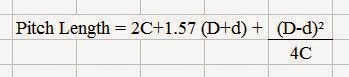
Calculating Drive Belt Length and Belt Horsepower Capability For An Auger
-Measure the center to center distance between the auger input shaft, and the motor shaft. (center to center distance the belt will have to span between the drive pulley and the driven pulley)
-Many auger manufacturers' catalogs often offer this measurement in the specifications section of their information.
(C) = Center to Center Distance
D = Drive Pulley Diameter
d = Driven Pulley Diameter
Note: The pitch length equation gives the required circumference for the belt at the midsection. The pitch diameter must be cross referenced in Chart X to determine the proper length for ordering belts.
Note: If the pitch length determined from the equation falls between the lengths given in chart No. X, choose the next larger belt.
Monday, May 6, 2013
Calculating Horsepower For an Incline Drag Conveyor
1. Determine overall ground length of drag conveyor
2. Multiply LENGTH X BUSHELS PER HOUR
3. Divide results by 55,000 - Write this total down.
4. Determine the discharge height in feet and multiply by the bushels per hour desired.
5. Divide the result by 26,500. - Write this total down.
6. If a curve section is used, divide the BPH desired by 1325.
(If no curve section is used, ignore step 6.)
7. Add the sums of the individual horsepowers to find the total horsepower.
The above formula has been found to be adequate for products such as shelled corn and soybeans. HEAVIER PRODUCTS MAY REQUIRE ADDITIONAL HORSEPOWER.
Formula example:
Overall length of the example conveyor is 50 feet. The discharge height of the conveyor is 7 feet from the bottom of the conveyor. There is a curve section used.
50 feet x 5000 bushels per hour = 250,000 divided by 55,000 = 4.5455
7 foot conveyor discharge height x 5000 bushels per hour = 35,000 divided by 26,500 = 1.3208
5000 bushels per hour divided by 1325 (curve section factor) = 3.7736
Add 4.5455 + 1.3208 + 3.7736 = 9.6399 total required horsepower (Round up to the nearest motor means this conveyor requires a 10 HP electric motor.)
Calculating Required Horsepower For a Horizontal Drag Conveyor
There are several ways to calculate horsepower for a drag chain conveyor in a grain handling application, however, I have found this shortcut for figuring horsepower for a horizontal drag conveyor to be one of the easiest to use.
1. Determine overall length of drag conveyor
2. Multiply LENGTH X BUSHELS PER HOUR
3. Divide results by 55,000
The above formula has been found to be adequate for products such as shelled corn and soybeans. HEAVIER PRODUCTS MAY REQUIRE ADDITIONAL HORSEPOWER.
Example:
50 foot overall length conveyor handling corn at 10,000 bushels per hour.
50 x 10,000 = 500,000
500,000 divided by 55,000 = 9.0909
Round up to nearest motor size means you would use a 10 horsepower electric motor.
Calculating Horsepower for a Bucket Elevator
Calculate Bucket Elevator Capacity
Thursday, August 16, 2012
Calculating Grain Bunker Volume and Capacity
Wednesday, August 15, 2012
Calculating Bucket Elevator Spout Length
Friday, June 22, 2012
Elevator Leg Spout Capacities
'*Note: The above information should be used as a guideline suggestion only. No liability is assumed for its use. All considerations mentioned above will alter spout capacity and must be allowed for. Spouting for ground feed and other fluffy materials should not be set at less than 50 degrees. Some of these materials have unusual characteristics. Spouting for almost all materials should be vented if the spout angle is 55 degrees or more.
Wednesday, June 13, 2012
Hydraulic Motor Size vs. RPM Calculation:
Gallons per minute of supply x 231
RPM = Cubic inches of motor displacement
Gallons per minute x 231
Motor cubic inches = RPM
RPM x cubic inches of motor displacement
GPM required = 231
PTO Shaft
A common question is, "How long can I expect my PTO shaft to last?" While there are many factors that contribute to that answer, there are a few rules of thumb that should be kept in mind.
Grease! Grease! Did I mention grease? The more often the better. The number one thing you can do to extend the life of your PTO shaft is to grease it often. Want to make sure it gets done? Hang a grease gun on the equipment with a PTO shaft.
Some information regarding how operating angle contributes to the life expectancy of a PTO shaft:
At 540 RPM and transmitting 40 HP, a category 4 PTO shaft at 22 degrees has a 12% decrease in life expectancy when the angle is changed by 3 degrees.
At 540 RPM and transmitting 24 HP, a category 3 PTO shaft at 22 degrees has a 22% decrease in life expectancy when the angle is changed by 6 degrees.
Thursday, April 5, 2012
Calculating Conveyor Angle
Enjoy!
Thursday, March 15, 2012
Screw Conveyor Lump Size Limitations
The character of the lump also is involved. Some materials have hard lumps that won't break up in transit through a screw conveyor. If that is the case, provision must be made to handle these lumps. Other materials may have lumps that are very hard, but degradable in transit through the screw conveyor, thus really reducing the lump size to be handled. Still other materials have lumps that are easily broken in a screw conveyor and therefore impose no limitations.
Three classes of lump sizes apply as follows:
Class I - A mixture of lumps and fines in which not more than 10% are lumps ranging from maximum size to one half of the maximum; and 90% are lumps smaller than one half of the maximum size.
Class II - A mixture of lumps and fines in which not more than 25% are lumps ranging from the maximum size to one half of the maximum; and 75% are lumps smaller than one half of the maximum size.
Class III - A mixture of lumps only in which 95% or more are lumps ranging from maximum size to one half of the maximum size; and 5% or less are lumps less than one tenth of the maximum size.
Table III shows the recommended maximum lump size for each customary screw diameter and the three lump classes. The ration, R, is included to show the average factor used for the normal screw diameters which then may be used as a guide for special screw sizes and constructions. For example:
Radial Clearance, Inches
Ratio, R = Lump Size, Inches
The allowable size of a lump in a screw conveyor is a function of the radial clearance between the outside diameter of the central pipe and the radius of the inside of the screw trough, as well as the proportion of lumps in the mix. The following illustration shows this relationship:
Friday, July 11, 2008
Bushels Per Hour to Tons Per Hour Formula
BPH x 1.25 = Cubic Feet Per Hour
Cubic Feet Per Hour x Pounds Per Cubic Feet = Pounds Per Hour
Pounds Per Hour / 2000 = Tons Per Hour
Common Assumed Per Cu Ft Weights:
Corn = 45 lbs per cubic ft
Feed = 35 lbs per cubic ft
Wheat = 48 lbs per cubic ft
Pellets = 55 to 60 lbs per cubic ft
(I highly recommend you VERIFY the weight of the material you will be conveying)
The above formula takes the form of an interactive calculator at sudenga.com: Click here to use this calculator.
Wednesday, January 30, 2008
Important Bucket Elevator Formulas
TO FIND LEG CAPACITY:
1. DETERMINE BELT SPEED IN FEET PER MINUTE
a. Motor RPM x motor pulley diameter, divided by driven pulley diameter = Input shaft speed to drive.
b. Divide Input shaft speed by Drive reduction ratio (15:1, 25:1, etc.) This gives the head shaft RPM.
c. Multiply the head shaft RPM x head pulley diameter in feet, x
3.1416. This gives the Belt speed in feet per minute.
2. FIND THE NUMBER OF CUPS FILLED IN ONE MINUTE:
a. Multiply feet per minute of belt speed x 12”, divided by cup spacing in inches.
b. Find cup capacity from Manufacturer’s chart in cubic feet.
Use water level + 10% or 75% of gross cup capacity.
c. Multiply cups filled per minute x cup capacity in cubic ft. This gives capacity of leg in one minute. Multiply result x 60 minutes
for hourly capacity in cubic feet.
d. For Bushels per hour, multiply cubic ft. per hour x .8
HORSEPOWER FORMULA FOR BUCKET ELEVATORS:
1. DISCHARGE HEIGHT IN FEET X BUSHELS PER HOUR,
Divided by 33,000 gives BARE HORSEPOWER
2. Multiply Bare Horsepower x 1.25 (safety factor) to get DESIGN
HORSEPOWER.
3. This calculation is based on grain weighing 60# per bushel.
ALTERNATE HORSEPOWER FORMULA:
1. Multiply DISCHARGE HEIGHT IN FEET X POUNDS OF MATERIAL
RAISED IN 1 MINUTE. Divided by 33,000 gives BARE HORSEPOWER.
2. Multiply Bare Horsepower by 1.25 (Safety Factor) for DESIGN
HORSEPOWER.
Wednesday, January 9, 2008
Calculate Horsepower For Inclined Screw Conveyors
Because of the incline of the screw, several conveying problems begin to occur.
1. The horsepower per unit of material increases
2. The efficiency of moving the material forward decreases.
A U-trough conveyor, because of its shape allows the material to flow back over the top of the screw when the angle of incline increases. This problem is complicated by the presence of the hanger bearing which speeds up this fall back.
One way to avoid this is through the use of a tubular housing, or round tube conveyor. This prevents the material from riding above the screw and slows the turbulence caused by the fall back. Although the type of material being conveyed greatly effects the amount of fall back incurred, a general area where the U-trough conveyor starts to lose significant efficiency is 15 degrees of incline.
Round tube conveyors are available with and without intermediate hanger bearings. One instance would be in the conveying of stringy or fibrous materials where the material will wrap around the bearing and eventually cause plugging. Elimination of the hanger bearing may cause excessive deflection of the central screw pipe and cause a vibration or chatter as a result of the screw hitting the tubing. This can be avoided by the introduction of most materials which will tend to lift and support the screw, provided the material is introduced upon start-up of the conveyor and fills the entire length. Care should be taken to empty the conveyor before shut-down to avoid overload start-up conditions.
Due to the fallback created in inclined screw conveyors by tumbling and agitation, the amount of material being pushed forward through the conveyor is reduced. To offset this loss of capacity, increased screw rotation is applied. This increased rotation creates a greater forward material velocity, the net result being greater capacity.
In general, as the angle of incline of the conveyor increases, the greater the loss in the percentage of fill of the screw.
The flowability of a material affects the percentage fo fill greatly. The greater the flowability, the more quickly the screw pitches become filled before conveying the material along the length of the screw. Also, at some inclines, depending on pitch and diameter, a section of the helical flight is actually at a near horizontal plane. This tends to slice or sling the material outward, rather than to move the material forward.
Several things can be done to maintain the fill percentage of an inclined conveyor.
1. Completely cover the screw intake to prevent spatter and fallback.
2. Increase the length of exposed intake screw.
3. Force feed the incline conveyor by means of a pressure fed boot supplied by a horizontal intake screw.
4. Use a close tolerance between screw and tube.
5. Increase RPM (revolutions per minute).
In general the horsepower and capacities of incline conveyors depends on the characteristics of the material being conveyed and may require consulting the manufacturer.
Horsepower, Inclined Conveyors
To calculate the horsepower of the inclined conveyor, use the method as described for horizontal conveyors. See this post.
HPF =
L X N X Fd X Fb
------------------
1,000,000
HPm =
C X L X W X Fm
------------------
1,000,000
Inclined conveyors require additional calculations to measure the horsepower required to elevate the material.
HPh =
C X W X H
-------------
1,980,000
Where: H = Discharge height in feet
Total Incline HP =
(HPf + HPm + HPh)
---------------------
e
Hanger Bearing Factors (Fb):
Ball Bearing - 1.0
Babbitt - 1.7
Bronze - 1.7
*Graphite bronze - 1.7
*Canvas base phenolic - 1.7
*Oil impregnated bronze - 1.7
*Oil impregnated wood - 1.7
*Plastic - 2.0
*Nylon - 2.0
*Teflon - 2.0
No bearings - 4.0
"*" = Non-lubricated bearings, or bearings not additionally lubricated.
Conveyor Diameter and Diameter Factor (Fd)
4.0 - 10
5.0 - 13
6.0 - 16
8.0 - 24
10.0 - 33
12.0 - 49
Tuesday, January 1, 2008
Horizontal Auger Horsepower Requirements
HORSEPOWER REQUIREMENTS, HORIZONTAL SCREW CONVEYORS
The horsepower required to operate a horizontal screw conveyor is based on proper installation, uniform and regular feed rate to the conveyor and other design criteria.
The following factors determine the horsepower requirements of a screw conveyor operating under the foregoing conditions.
C = Capacity in cubic feet per hour.
e = Drive efficiency.
Fb = Hanger bearing factor.
Fd = Conveyor diameter factor.
Fm = Material factor
L = Total length of conveyor, feet.
N = Operating speed, RPM (revolutions per minute).
W = Apparent density of the material as conveyed, lbs, per cubic foot.
The horsepower requirement is the total of the horsepower to overcome conveyor friction (HPf) and the horsepower to transport the material at the specified rate (HPm), divided by the total drive efficiency, e, or:
HPf =
LN Fd Fb
------------
1,000,000
HPm =
CLW Fm
------------
1,000,000
Total HP =
(HPf + HPm)
---------------
e
Note: Inclined Auger HP Requirements are higher than for horizontal augers.
It is apparent that with conveyor capacity, size, speed, and length, all known that factors Fm, Fd and Fb are quite important. Small changes in these factors cause significant changes in the required horsepower. A discussion of these factors follows.
The factor Fb is related to the friction in the hanger bearing, due to rubbing of the journals in the bearing metal and including, for sleeve type hanger bearings, an allowance for the entry into the bearing of some foreign material. This factor is empirically derived.
Factor Fd has been computed proportional to the average weight per foot of the heaviest rotating parts and to the coupling shaft diameter.
The factor Fm depends upon the characteristics of the material. It is an entirely empirical factor determined by long experience in designing and operating screw conveyors. It has no measurable relation to any physical property of the material transported.
While it is good procedure in conveying of bulk materials to run the conveyor until it is empty, prior to a work stoppage, frequently conveyors must of necessity be stopped while fully loaded. In that event, starting the conveyor again may possibly cause a serious overloading of the Drive and motor. The characteristics of the material have much to do with the restarting of a fully loaded screw conveyor. Some materials will settle and pack or otherwise change their "as conveyed" characteristics. For example, Portland cement may take on the characteristics of a solid. Granulated sugar may pick up moisture from the atmosphere and form a crust or cake. These situations will require a larger than normal driving motor.
It is important that a conveyor system operate as demanded by its controls. Start-up conditions or temporary overloads should not cause interruptions in service, so all components of the drive, as well as, the motor, should be chosen accordingly.
It is generally accepted practice that most power transmitting elements of a screw conveyor be sized and selected to handle safely the rated motor horsepower. If, for example, a screw conveyor requires 3.5 horsepower as determined by the horsepower formula, a 5 horsepower motor must be used, and it is desirable that all power transmitting elements be capable of safely handling the full 5 horsepower. However, on a screw conveyor made up of several lengths of conveyor screw, only the drive shaft has to handle the full motor load. The succeeding screw lengths and couplings only have to handle loads proportionate to the distance these parts are from the drive shaft. For economy, ease of design and maintenance, it is usual to select conveyor couplings, coupling bolts and other rotating parts such that all are of the same size and interchangeable, even if they are a bit larger than necessary.
NOTE: The foregoing load carrying requirements really constitute a minimum shock loading, metal fatigue from 24 hour per day continuous service, etc., must be considered in addition.